PWM Explained the Way Industry Actually Uses It
Pulse Width Modulation (PWM) looks simple on paper, but in real products it decides efficiency, reliability, and safety. This blog breaks PWM beyond duty cycle formulas, showing how industry engineers actually use it to control energy, motors, and power systems. If you’ve “used PWM” but never thought about load dynamics, feedback, and failures, this will change how you see it.
Arshia Sharma
1/26/20266 min read


PWM Explained the Way Industry Actually Uses It
Why Pulse Width Modulation Is Not as Simple as You Were Taught — and Why That Matters in Real Products
Introduction: PWM Is Easy to Learn, Painfully Hard to Use Correctly
Pulse Width Modulation, commonly abbreviated as PWM, is often introduced as one of the simplest ideas in electronics and embedded systems: a digital signal that switches ON and OFF at a fixed frequency, where the ratio of ON time to OFF time determines the “effective” output.
Because of this simplified explanation, many engineers walk into the industry believing they already understand PWM. And yet, once they start working on real hardware — motors, power supplies, automotive controllers, LED drivers, or industrial actuators — PWM suddenly becomes the source of unexplained noise, overheating, EMI failures, unstable control loops, and devices that behave perfectly on the bench but fail in the field.
The truth is simple but uncomfortable:
PWM is not difficult to generate, but it is extremely easy to misuse if you don’t understand the system it is driving.
This blog explains PWM the way industry actually uses it, not as a timer feature in a microcontroller, but as a system-level energy control mechanism that interacts with electronics, magnetics, mechanics, thermal behavior, and feedback loops.
What PWM Really Is (And Why the Usual Definition Is Incomplete)
At a surface level, PWM is described as a digital waveform that alternates between a high and a low voltage at a fixed frequency, where the width of the high pulse within each cycle determines the output behavior. While this description is technically correct, it is dangerously incomplete for anyone building real products.
In industry, PWM is not treated as “a signal.”
It is treated as a method of controlling how much energy is delivered to a load over time.
That load could be:
A resistive heater
An LED with strict current limits
A motor winding with inductance and back-EMF
A transformer in a switch-mode power supply
A solenoid or valve in an automotive system
The moment you recognize that PWM is fundamentally about energy transfer, not voltage generation, you begin to understand why so many real-world PWM designs fail when approached casually.
Duty Cycle: What It Is, What It Isn’t, and Why Industry Cares Deeply About It
The Formal Definition
The duty cycle of a PWM signal is defined as the percentage of one complete switching period during which the signal remains in its active (ON or high) state.
Mathematically:
Duty Cycle (%) = (ON Time / Total Period) × 100
If a PWM signal has a period of 1 millisecond and stays high for 0.25 milliseconds, the duty cycle is 25%.
This definition is correct — but it does not explain what duty cycle does in a real system.
The Dangerous Oversimplification
In academic settings, duty cycle is often explained using the equation:
Average Voltage = Duty Cycle × Supply Voltage
This relationship only holds under extremely limited conditions, typically when the load is purely resistive and when dynamic effects such as inductance, capacitance, switching losses, and feedback loops are ignored. In industry, duty cycle does not directly represent voltage in most applications. Instead, it controls how much energy is injected into a system per unit time, and the final observable output (speed, brightness, temperature, torque, pressure) is the result of how that system responds to the injected energy.
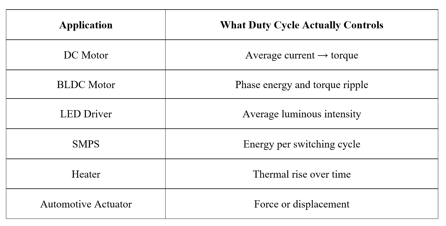
What Duty Cycle Controls in Real Products
This is why two systems with the same duty cycle can behave completely differently, and why copying PWM values from one design to another often ends in failure.
How Duty Cycle Is Controlled in Industry
In most real products, duty cycle is never fixed. It is continuously adjusted by firmware or control logic based on feedback from the system.
Open-Loop Duty Cycle (Rare in Professional Products)
Open-loop PWM means:
Duty cycle is set once
No feedback is used
Output depends entirely on supply voltage and load conditions
This approach is fragile and is typically limited to:
Very low-cost devices
Non-critical loads
Short-lived prototypes
Temperature changes, aging components, or supply fluctuations quickly make open-loop PWM unreliable.
Closed-Loop Duty Cycle Control (Industry Standard)
In professional systems, duty cycle is almost always controlled by a feedback loop.
The general process looks like this:
A sensor measures the system output (speed, current, voltage, temperature).
The measured value is compared with a target value.
An error is calculated.
A control algorithm (often PID) computes a new duty cycle.
The PWM hardware updates the output.
In this context, duty cycle is not a static parameter — it is a real-time control variable that may change thousands of times per second.
PWM Frequency: A Design Choice With Serious Consequences
One of the most common beginner mistakes is treating PWM frequency as an arbitrary value that can be chosen without much thought. In industry, PWM frequency is a carefully selected design parameter that affects efficiency, noise, EMI, thermal behavior, and even regulatory compliance.
Factors That Influence PWM Frequency Selection
Load inductance and time constant
Audible noise constraints
Switching losses in MOSFETs or IGBTs
ADC sampling synchronization
EMC and EMI regulations
Processor load and timer resolution
Choosing the wrong frequency can result in:
Audible whining from motors or inductors
Excessive heating of power devices
Failed EMC certification
Unstable control loops
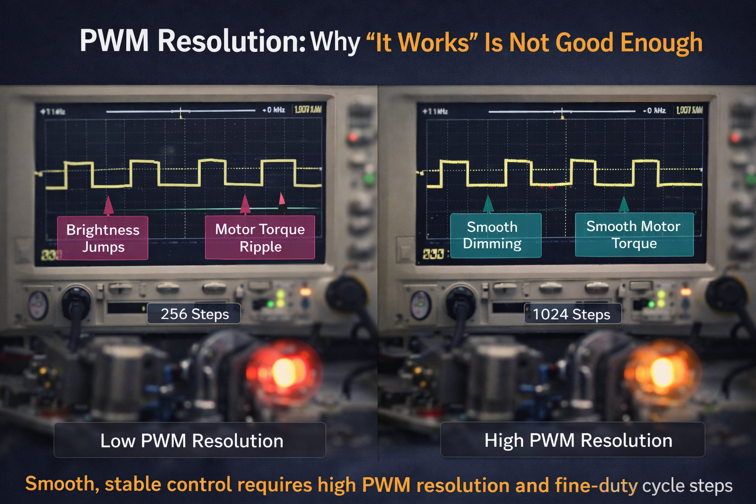
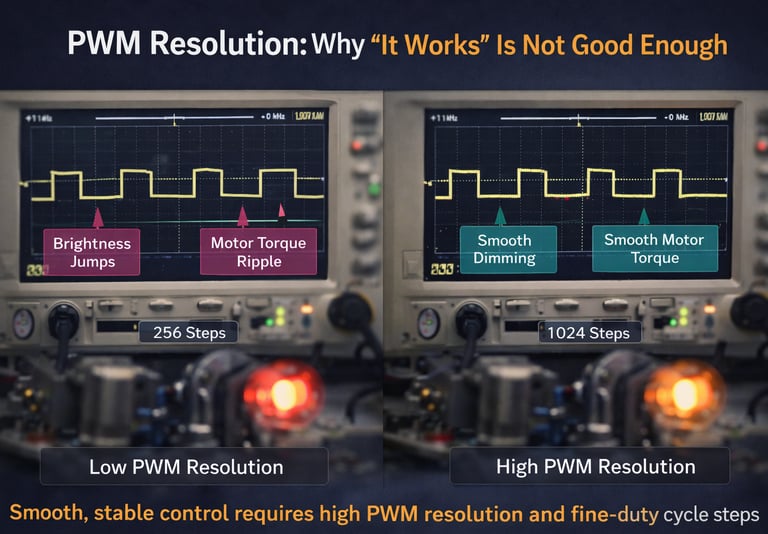
PWM Resolution: Why “It Works” Is Not Good Enough
PWM resolution refers to how finely the duty cycle can be adjusted, and it is determined by the timer resolution of the microcontroller or control IC.
A low-resolution PWM may technically function, but it often introduces:
Torque ripple in motors
Visible steps in LED brightness
Control instability near setpoints
Industry designs frequently balance PWM frequency and resolution to ensure smooth control without overloading the processor or degrading efficiency.
PWM and Inductance: The Silent Partner in Almost Every System
Inductance is the reason PWM works at all in most real applications.
In motors, inductance smooths current.
In power supplies, inductance stores and transfers energy.
In EMI filtering, inductance suppresses high-frequency noise.
Without inductance, PWM would simply produce rapid voltage switching with no meaningful control outcome. Understanding how inductance interacts with PWM is one of the key differences between a hobbyist design and a professional one.
Why PWM Without Feedback Is a Liability
A PWM signal by itself has no awareness of:
Load changes
Temperature rise
Component aging
Fault conditions
This is why industrial systems always include:
Current sensing
Voltage feedback
Temperature monitoring
Fault detection
PWM is the actuator, not the brain. Treating it as the final solution rather than part of a closed system is a common and costly mistake.
PWM in Motors: Controlling Torque, Not Speed
One of the most persistent myths in embedded education is that PWM directly controls motor speed. In reality, PWM controls motor current, which in turn controls torque. Speed is an indirect result of torque overcoming load and losses.
This misunderstanding leads to poor motor control designs that:
Stall under load
Overheat at low speeds
Respond unpredictably to disturbances
Industry motor control focuses on current regulation first, speed control second.
PWM in Power Electronics: Energy Per Cycle Matters More Than Voltage
In switch-mode power supplies, PWM determines how much energy is transferred through inductors and transformers during each switching cycle. The output voltage is a result of:
Duty cycle
Input voltage
Load demand
Control loop dynamics
This is why SMPS design requires deep understanding of control theory, not just PWM generation.
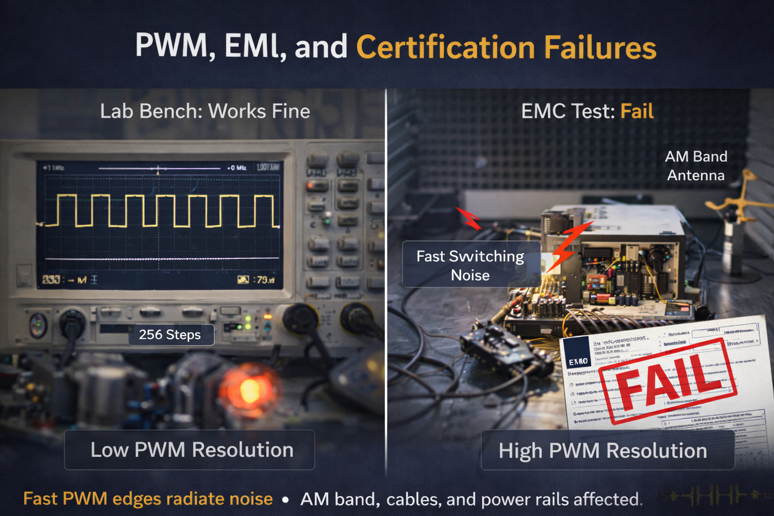
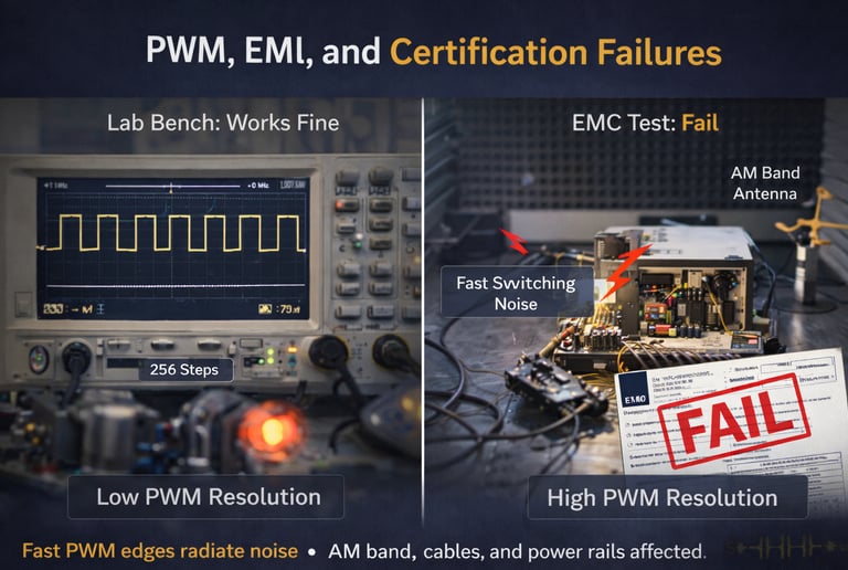
PWM, EMI, and Certification Failures
PWM creates fast voltage transitions, which are a major source of electromagnetic interference. Products that work perfectly in the lab often fail compliance testing because PWM edges inject noise into power rails, cables, and ground planes.
Industry solutions include:
Controlled edge rates
Snubber circuits
Spread-spectrum PWM
Careful PCB layout
Ignoring these aspects is one of the fastest ways to turn a functional prototype into a failed product.
How Interviewers Know You Don’t Really Understand PWM
Experienced interviewers listen carefully for how candidates talk about PWM.
Red flags include:
Treating PWM as “analog voltage”
Ignoring load behavior
Assuming duty cycle equals output directly
Overlooking feedback and protection
Strong candidates describe PWM as part of a system, not a standalone feature.
Why Most Courses Still Teach PWM Incorrectly
Educational material often focuses on:
Timer registers
Duty cycle percentages
Simple LED demos
What it rarely teaches is:
Energy flow
Load dynamics
Control stability
Failure modes
Industry engineers learn PWM not from textbooks, but from burnt MOSFETs, noisy motors, and failed compliance tests.
Final Thought: PWM Is a Responsibility, Not a Convenience
PWM is deceptively simple to generate and dangerously easy to misuse. In real products, it influences efficiency, reliability, safety, and regulatory success.
If you truly understand PWM, you understand:
Embedded systems
Power electronics
Control theory
System-level design
And that is exactly why industry treats PWM with respect.
PWM isn’t just about turning things ON and OFF — it’s about controlling energy, safely and intelligently, in an imperfect real world.